Product Description
The 3.3V Adapter Board for NRF24L01 is a dedicated power management module designed to solve the common stability issues associated with high-power wireless transceivers. While the NRF24L01 operates strictly on 3.3V, it often suffers from communication failures when powered by the weak 3.3V rail of an Arduino. This adapter features an on-board AMS1117-3.3V regulator that allows you to power your wireless module from a stable 5V or even a 12V source. With integrated decoupling capacitors and a standard 2x4 female socket, it ensures a clean, ripple-free power supply for long-range, error-free wireless data transmission.
Key Features
Stable 3.3V Regulation: Converts unstable 5V-12V inputs into a precise 3.3V output specifically for the NRF24L01+ transceiver.
On-board Filtering: Features both SMD and electrolytic filtering capacitors to suppress power noise and prevent wireless signal dropping.
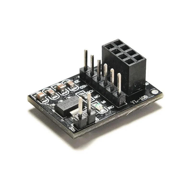
Plug-and-Play Socket: Equipped with a 2x4 (8-pin) female header, allowing the NRF24L01 module to be plugged in directly without messy wiring.
Power Indicator LED: Built-in SMD LED provides instant visual confirmation that the adapter is receiving power.
Enhanced Range Support: Provides the necessary current (up to 800mA) required for "PA+LNA" (Power Amplifier) versions of the NRF24L01, which the standard Arduino 3.3V pin cannot provide.