4-20mA to 5V Converter for Arduino Industrial Sensor Interface Board
| Feature | Details |
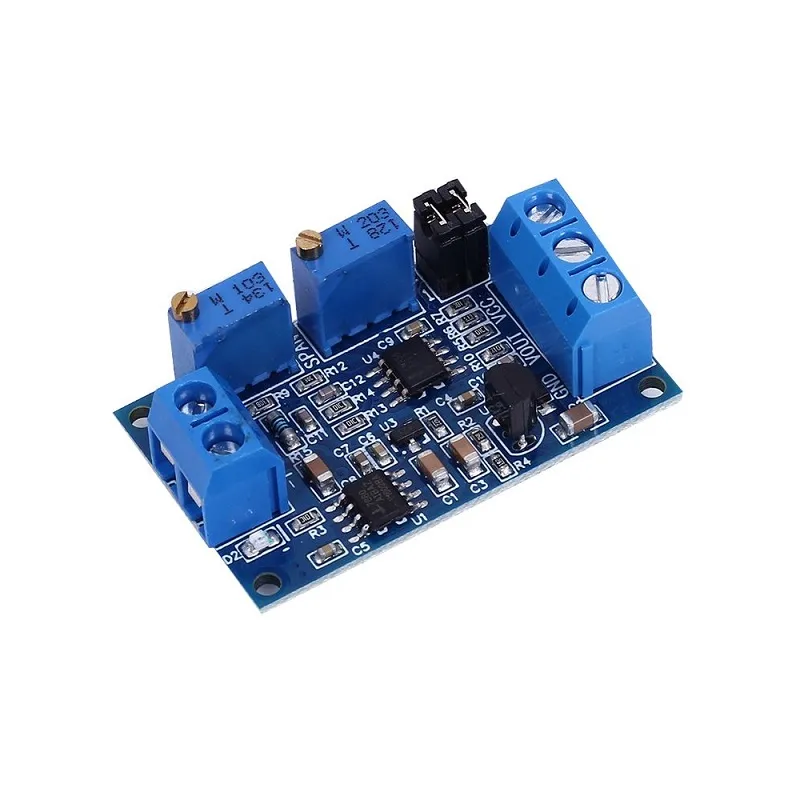
| Input Signal | 4mA to 20mA (Industrial Standard) |
| Output Signal | 0V to 3.3V / 5V / 10V (Adjustable) |
| Supply Voltage | 7V to 35V DC |
| Onboard IC | High-Precision Operational Amplifier |
| Calibration | Zero and Span Adjustment Potentiometers |
| Protection | Reverse Polarity & Surge Protection |