Arduino Ultrasonic Distance Meter DIY Kit
🚚 FREE Delivery on Orders Above ₹499
📦 Pan India Delivery
Build it. Move an object. Watch the distance change.
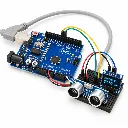
Build a USB-powered distance meter and discover how an Arduino reads an ultrasonic sensor and displays measurements on an OLED.
Aim the HC-SR04 at a flat object. The display updates continuously in centimetres as you move the object. No measurement button is required.
Your UNO SMD compatible board arrives pre-programmed. Follow the assembly and wiring steps; a computer is optional for normal operation.
The OLED pins arrive soldered. Use the supplied 170-point mini breadboard and ten male-to-male jumper wires to connect the modules.
Arrange a suitable USB power source. This is an educational demonstration kit. A mounting base is optional; use your own cardboard sheet if desired.
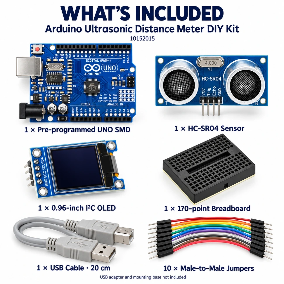
Lay out the components before you begin. All ten jumper wires are used in the shared-power arrangement described here.
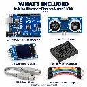
| Item | Quantity / details |
|---|---|
| UNO-compatible SMD board | 1 — Pre-programmed |
| HC-SR04 ultrasonic sensor | 1 — Distance sensing |
| 0.96-inch I²C OLED | 1 — 128 × 64; pins soldered |
| 170-point mini breadboard | 1 — Black; solderless |
| USB-A to USB-B cable | 1 — 20 cm |
| Male-to-male jumper wires | 10 — Breadboard connections |
A suitable USB power source. A USB adapter, batteries, mounting base, enclosure, adhesive and mounting hardware are not included. No loose male header strip, external LEDs or buzzer are included.
The supplied breadboard is the 170-point mini version. Larger breadboards and PVC bases seen in reference assemblies are not supplied. You can use your own cardboard sheet as an optional base.
Follow these steps in order. Disconnect USB before making or changing any connection.
Lay out the six component groups listed above. Keep the USB cable disconnected throughout assembly. Identify the labels on the HC-SR04 and OLED before inserting either module.
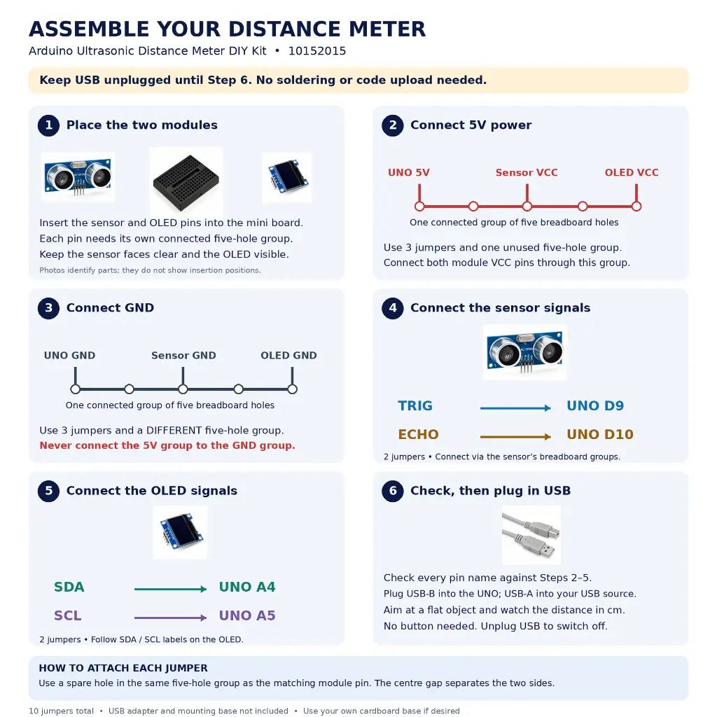
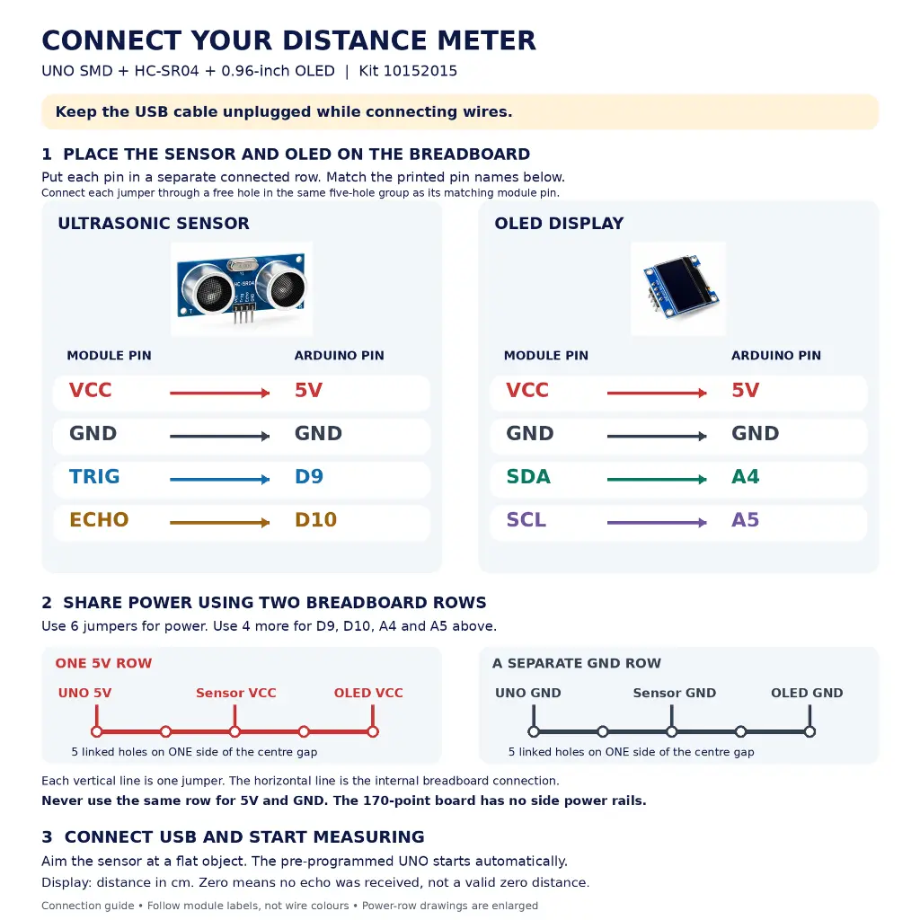
Insert the sensor and OLED into the 170-point breadboard with each pin in its own connected five-hole group. Keep the sensor faces clear and the display visible. Do not place two different module pins in the same connected group.
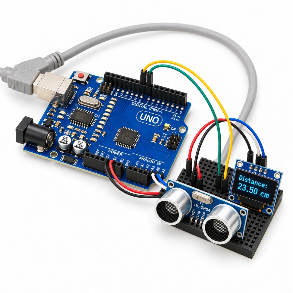
Choose one unused five-hole group on one side of the centre gap. Use three jumpers: UNO 5V → this group; this group → HC-SR04 VCC; this group → OLED VCC. At the module end, insert the jumper in a free hole connected to that module’s VCC pin.
Choose a different unused five-hole group. Use three jumpers: UNO GND → this group; this group → HC-SR04 GND; this group → OLED GND. Keep the 5V group completely separate from the GND group.
Use the four remaining jumpers: HC-SR04 TRIG → UNO D9; HC-SR04 ECHO → UNO D10; OLED SDA → UNO A4; OLED SCL → UNO A5. Connect through free holes in the same groups as the matching module pins.
Check all connections against the guide below. Make sure no loose pins or wires can touch. Connect the USB-B end to the UNO and the USB-A end to your USB power source. Measurement starts automatically.
Aim the sensor at a flat, rigid target such as a book cover. Move the target gradually and watch the reading change. For a ruler comparison, measure from the sensor’s front faces. Disconnect USB to switch off.
Every module pin needs its own connected five-hole group. Connect a jumper through a spare hole in the same group as its matching pin. Do not short different module pins together.
Optional: support the project on your own cardboard base. Keep the UNO’s underside away from metal, the sensor faces unobstructed and the OLED visible.
Read the printing on each module. Wire colours are only visual aids; follow the pin names.
| Module connection | Arduino connection |
|---|---|
| HC-SR04 VCC | UNO 5V via shared 5V group |
| HC-SR04 GND | UNO GND via shared GND group |
| HC-SR04 TRIG | UNO D9 |
| HC-SR04 ECHO | UNO D10 |
| OLED VCC | UNO 5V via shared 5V group |
| OLED GND | UNO GND via shared GND group |
| OLED SDA | UNO A4 |
| OLED SCL | UNO A5 |
UNO 5V → shared group → sensor VCC + OLED VCC
UNO GND → separate group → sensor GND + OLED GND
Use three jumpers for the 5V connections, three for GND, and four for the signal connections. Never join the 5V group to the GND group.
The 170-point breadboard has no side power rails. Five holes within each row on one side of the centre gap connect together; the other side is a separate group.
Keep the assembly on a clean, dry, non-conductive surface. Check all wiring before connecting USB.
Plug the USB-B connector into the UNO and the USB-A connector into your USB power source. The pre-programmed board begins measuring automatically; no button is needed.
Aim the sensor at a flat, rigid object such as a book cover or stiff cardboard. Hold it facing the sensor and keep your wires still.
Move the target gradually and observe the centimetre reading. If comparing with a ruler, measure from the front faces of the ultrasonic transducers, not the edge of your base.
When the supplied program receives no echo before timing out, it calculates zero. This is not a real measurement of zero centimetres. Check the target and connections if it persists.
No tested minimum range, maximum range or accuracy guarantee has been supplied for the assembled kit. Decimal places on the OLED do not establish measurement accuracy.
The supplied program waits 500 ms after each display update. Total refresh time also includes the echo measurement and display update. There is no external warning LED or buzzer.
Your board is already programmed. The supplied sketch below retains your original program logic and pin assignments.
#include <Wire.h>
#include <Adafruit_GFX.h>
#include <Adafruit_SSD1306.h>
#define SCREEN_WIDTH 128
#define SCREEN_HEIGHT 64
Adafruit_SSD1306 display(SCREEN_WIDTH, SCREEN_HEIGHT, &Wire, -1);
#define TRIG 9
#define ECHO 10
long duration;
float distance;
void setup() {
pinMode(TRIG, OUTPUT);
pinMode(ECHO, INPUT);
Serial.begin(9600);
if(!display.begin(SSD1306_SWITCHCAPVCC, 0x3C)) {
Serial.println("OLED not found");
while(true);
}
display.clearDisplay();
}
void loop() {
digitalWrite(TRIG, LOW);
delayMicroseconds(2);
digitalWrite(TRIG, HIGH);
delayMicroseconds(10);
digitalWrite(TRIG, LOW);
duration = pulseIn(ECHO, HIGH);
distance = duration * 0.034 / 2;
display.clearDisplay();
display.setTextSize(2);
display.setTextColor(WHITE);
display.setCursor(10, 10);
display.print("Distance:");
display.setCursor(30, 40);
display.print(distance);
display.print(" cm");
display.display();
delay(500);
}
Sensor: TRIG D9, ECHO D10. OLED: SDA A4, SCL A5; SSD1306, 128 × 64, address 0x3C.
The sketch uses Wire, Adafruit GFX Library and Adafruit SSD1306. Wire is included with the Arduino board software. Install the two Adafruit libraries and prompted dependencies through the Arduino IDE Library Manager before compiling.
Connect the UNO to your computer, select Arduino Uno and the matching port in Arduino IDE, open or paste this sketch, verify and upload. Uploading replaces the installed program. This is not needed for first assembly.
The sketch measures echo duration and calculates distance using duration × 0.034 ÷ 2. A timed-out echo produces zero. Large fixed-size text can wrap for longer readings; preserve a copy before experimenting with display formatting.
Select the symptom below. Disconnect USB before changing wiring.
Disconnect USB. Check VCC/GND, then SDA → A4 and SCL → A5. Check that each module pin and its jumper share a connected breadboard group. Reconnect power. If you changed the code, check the configured display type and address 0x3C.
Check HC-SR04 power, TRIG → D9 and ECHO → D10. Aim the sensor at a flat object. Check loose jumpers and make sure different module pins are not shorted together in one breadboard group.
Keep the sensor and test object still. Try a larger, flatter target facing the sensor. Check for loose contacts and nearby objects in front of the sensor.
Check both USB connections and try another suitable USB source or known-working cable. Disconnect power before inspecting the wiring for an accidental short.
For optional reprogramming, install Adafruit GFX Library and Adafruit SSD1306 through the Arduino IDE Library Manager, including prompted dependencies.
The supplied sketch uses large text at fixed positions. Longer values may wrap; this is a display-formatting issue. Keep a copy of the supplied sketch before changing text size or cursor positions.
If copying is blocked, select the sketch and copy it manually. If the code becomes selected after clicking Copy, press Ctrl+C or use your device’s Copy command. The board is already programmed, so normal kit operation does not depend on these buttons.
Contact RoboGears through the contact option on this website. Share your order reference, a clear wiring photo with pin labels visible, and a description or short video of the OLED behaviour. Include error text if you changed the program.
25 answers
Yes. The included UNO-compatible SMD board comes pre-programmed for this distance meter. You do not need to upload code for the first assembly.
It continuously measures the distance to a reflecting object and displays the reading in centimetres on the OLED. It is intended for educational demonstrations.
The kit uses a 0.96-inch, 128 × 64 I²C OLED. A 16 × 2 LCD and separate LCD interface board are not included.
No. Measurement starts automatically when the correctly wired project receives USB power.
The supplied program displays centimetres only.
In the supplied program, a zero reading means the sensor did not return an echo before the measurement timed out. It must not be interpreted as an actual zero-centimetre distance.
One black 170-point mini breadboard is included. Larger breadboards visible in reference assemblies are not supplied.
No. You can use your own cardboard sheet as an optional base. A PVC sheet, enclosure, mounting hardware and adhesive are not included.
No. The OLED pins arrive soldered. Assemble the kit using the supplied breadboard and male-to-male jumper wires.
Ten male-to-male jumpers are included. The guide uses six for shared power and ground, and four for the signal connections.
Insert the module pins into the breadboard. Insert each jumper into a spare hole in the same connected five-hole group as the matching module pin. The other end connects to the UNO or the shared power group.
Use one free five-hole breadboard group for 5V: connect the UNO 5V pin and the two module VCC connections to that group. Use a different group for the three GND connections.
No. Use separate five-hole groups for power and ground. The five holes on each side of the centre gap are connected within that row; the gap separates the two sides.
HC-SR04 VCC → UNO 5V, GND → GND, TRIG → D9 and ECHO → D10.
OLED VCC → UNO 5V, GND → GND, SDA → A4 and SCL → A5. Follow the pin names printed on the supplied module.
No. The kit includes a 20 cm USB-A to USB-B cable. Supply your own suitable USB power source.
Disconnect USB power. No separate power switch is included.
Yes. Once assembled, the pre-programmed board can run from a suitable USB power source without a computer. A computer is needed if you want to edit and upload the program.
No external buzzer or warning LEDs are included or used by the supplied program. The UNO’s onboard indicators are separate from distance measurement.
Use a flat, rigid object such as a book cover or a piece of stiff cardboard. Hold it facing the sensor and move it gradually while watching the display.
Use the front faces of the ultrasonic transducers as the reference point for your demonstration, rather than the edge of your cardboard base.
No verified range or accuracy specification is provided for this assembled kit. Use it to learn and demonstrate distance sensing, and compare readings with a ruler for your own experiments.
Yes. The supplied sketch is available in the code section with Copy code and Download .ino controls. Save a copy before making changes. Keep wiring and pin definitions consistent.
Wire, Adafruit GFX Library and Adafruit SSD1306. Wire is part of the Arduino board software; install the two Adafruit libraries and any prompted dependencies through the Arduino IDE Library Manager if you want to upload the sketch.
Share your order reference, a clear photo showing all connections and printed pin labels, and a short video or description of the display behaviour. Include any compile or upload error text if you changed the program.
No matching answer. Try a shorter term such as OLED, sensor or power.
Build it. Move an object. Watch the distance change.
Build a USB-powered distance meter and discover how an Arduino reads an ultrasonic sensor and displays measurements on an OLED.
Aim the HC-SR04 at a flat object. The display updates continuously in centimetres as you move the object. No measurement button is required.
Your UNO SMD compatible board arrives pre-programmed. Follow the assembly and wiring steps; a computer is optional for normal operation.
The OLED pins arrive soldered. Use the supplied 170-point mini breadboard and ten male-to-male jumper wires to connect the modules.
Arrange a suitable USB power source. This is an educational demonstration kit. A mounting base is optional; use your own cardboard sheet if desired.
Lay out the components before you begin. All ten jumper wires are used in the shared-power arrangement described here.
| Item | Quantity / details |
|---|---|
| UNO-compatible SMD board | 1 — Pre-programmed |
| HC-SR04 ultrasonic sensor | 1 — Distance sensing |
| 0.96-inch I²C OLED | 1 — 128 × 64; pins soldered |
| 170-point mini breadboard | 1 — Black; solderless |
| USB-A to USB-B cable | 1 — 20 cm |
| Male-to-male jumper wires | 10 — Breadboard connections |
A suitable USB power source. A USB adapter, batteries, mounting base, enclosure, adhesive and mounting hardware are not included. No loose male header strip, external LEDs or buzzer are included.
The supplied breadboard is the 170-point mini version. Larger breadboards and PVC bases seen in reference assemblies are not supplied. You can use your own cardboard sheet as an optional base.
Follow these steps in order. Disconnect USB before making or changing any connection.
Lay out the six component groups listed above. Keep the USB cable disconnected throughout assembly. Identify the labels on the HC-SR04 and OLED before inserting either module.
Insert the sensor and OLED into the 170-point breadboard with each pin in its own connected five-hole group. Keep the sensor faces clear and the display visible. Do not place two different module pins in the same connected group.
Choose one unused five-hole group on one side of the centre gap. Use three jumpers: UNO 5V → this group; this group → HC-SR04 VCC; this group → OLED VCC. At the module end, insert the jumper in a free hole connected to that module’s VCC pin.
Choose a different unused five-hole group. Use three jumpers: UNO GND → this group; this group → HC-SR04 GND; this group → OLED GND. Keep the 5V group completely separate from the GND group.
Use the four remaining jumpers: HC-SR04 TRIG → UNO D9; HC-SR04 ECHO → UNO D10; OLED SDA → UNO A4; OLED SCL → UNO A5. Connect through free holes in the same groups as the matching module pins.
Check all connections against the guide below. Make sure no loose pins or wires can touch. Connect the USB-B end to the UNO and the USB-A end to your USB power source. Measurement starts automatically.
Aim the sensor at a flat, rigid target such as a book cover. Move the target gradually and watch the reading change. For a ruler comparison, measure from the sensor’s front faces. Disconnect USB to switch off.
Every module pin needs its own connected five-hole group. Connect a jumper through a spare hole in the same group as its matching pin. Do not short different module pins together.
Optional: support the project on your own cardboard base. Keep the UNO’s underside away from metal, the sensor faces unobstructed and the OLED visible.
Read the printing on each module. Wire colours are only visual aids; follow the pin names.
| Module connection | Arduino connection |
|---|---|
| HC-SR04 VCC | UNO 5V via shared 5V group |
| HC-SR04 GND | UNO GND via shared GND group |
| HC-SR04 TRIG | UNO D9 |
| HC-SR04 ECHO | UNO D10 |
| OLED VCC | UNO 5V via shared 5V group |
| OLED GND | UNO GND via shared GND group |
| OLED SDA | UNO A4 |
| OLED SCL | UNO A5 |
UNO 5V → shared group → sensor VCC + OLED VCC
UNO GND → separate group → sensor GND + OLED GND
Use three jumpers for the 5V connections, three for GND, and four for the signal connections. Never join the 5V group to the GND group.
The 170-point breadboard has no side power rails. Five holes within each row on one side of the centre gap connect together; the other side is a separate group.
Keep the assembly on a clean, dry, non-conductive surface. Check all wiring before connecting USB.
Plug the USB-B connector into the UNO and the USB-A connector into your USB power source. The pre-programmed board begins measuring automatically; no button is needed.
Aim the sensor at a flat, rigid object such as a book cover or stiff cardboard. Hold it facing the sensor and keep your wires still.
Move the target gradually and observe the centimetre reading. If comparing with a ruler, measure from the front faces of the ultrasonic transducers, not the edge of your base.
When the supplied program receives no echo before timing out, it calculates zero. This is not a real measurement of zero centimetres. Check the target and connections if it persists.
No tested minimum range, maximum range or accuracy guarantee has been supplied for the assembled kit. Decimal places on the OLED do not establish measurement accuracy.
The supplied program waits 500 ms after each display update. Total refresh time also includes the echo measurement and display update. There is no external warning LED or buzzer.
Your board is already programmed. The supplied sketch below retains your original program logic and pin assignments.
#include <Wire.h>
#include <Adafruit_GFX.h>
#include <Adafruit_SSD1306.h>
#define SCREEN_WIDTH 128
#define SCREEN_HEIGHT 64
Adafruit_SSD1306 display(SCREEN_WIDTH, SCREEN_HEIGHT, &Wire, -1);
#define TRIG 9
#define ECHO 10
long duration;
float distance;
void setup() {
pinMode(TRIG, OUTPUT);
pinMode(ECHO, INPUT);
Serial.begin(9600);
if(!display.begin(SSD1306_SWITCHCAPVCC, 0x3C)) {
Serial.println("OLED not found");
while(true);
}
display.clearDisplay();
}
void loop() {
digitalWrite(TRIG, LOW);
delayMicroseconds(2);
digitalWrite(TRIG, HIGH);
delayMicroseconds(10);
digitalWrite(TRIG, LOW);
duration = pulseIn(ECHO, HIGH);
distance = duration * 0.034 / 2;
display.clearDisplay();
display.setTextSize(2);
display.setTextColor(WHITE);
display.setCursor(10, 10);
display.print("Distance:");
display.setCursor(30, 40);
display.print(distance);
display.print(" cm");
display.display();
delay(500);
}
Sensor: TRIG D9, ECHO D10. OLED: SDA A4, SCL A5; SSD1306, 128 × 64, address 0x3C.
The sketch uses Wire, Adafruit GFX Library and Adafruit SSD1306. Wire is included with the Arduino board software. Install the two Adafruit libraries and prompted dependencies through the Arduino IDE Library Manager before compiling.
Connect the UNO to your computer, select Arduino Uno and the matching port in Arduino IDE, open or paste this sketch, verify and upload. Uploading replaces the installed program. This is not needed for first assembly.
The sketch measures echo duration and calculates distance using duration × 0.034 ÷ 2. A timed-out echo produces zero. Large fixed-size text can wrap for longer readings; preserve a copy before experimenting with display formatting.
Select the symptom below. Disconnect USB before changing wiring.
Disconnect USB. Check VCC/GND, then SDA → A4 and SCL → A5. Check that each module pin and its jumper share a connected breadboard group. Reconnect power. If you changed the code, check the configured display type and address 0x3C.
Check HC-SR04 power, TRIG → D9 and ECHO → D10. Aim the sensor at a flat object. Check loose jumpers and make sure different module pins are not shorted together in one breadboard group.
Keep the sensor and test object still. Try a larger, flatter target facing the sensor. Check for loose contacts and nearby objects in front of the sensor.
Check both USB connections and try another suitable USB source or known-working cable. Disconnect power before inspecting the wiring for an accidental short.
For optional reprogramming, install Adafruit GFX Library and Adafruit SSD1306 through the Arduino IDE Library Manager, including prompted dependencies.
The supplied sketch uses large text at fixed positions. Longer values may wrap; this is a display-formatting issue. Keep a copy of the supplied sketch before changing text size or cursor positions.
If copying is blocked, select the sketch and copy it manually. If the code becomes selected after clicking Copy, press Ctrl+C or use your device’s Copy command. The board is already programmed, so normal kit operation does not depend on these buttons.
Contact RoboGears through the contact option on this website. Share your order reference, a clear wiring photo with pin labels visible, and a description or short video of the OLED behaviour. Include error text if you changed the program.
25 answers
Yes. The included UNO-compatible SMD board comes pre-programmed for this distance meter. You do not need to upload code for the first assembly.
It continuously measures the distance to a reflecting object and displays the reading in centimetres on the OLED. It is intended for educational demonstrations.
The kit uses a 0.96-inch, 128 × 64 I²C OLED. A 16 × 2 LCD and separate LCD interface board are not included.
No. Measurement starts automatically when the correctly wired project receives USB power.
The supplied program displays centimetres only.
In the supplied program, a zero reading means the sensor did not return an echo before the measurement timed out. It must not be interpreted as an actual zero-centimetre distance.
One black 170-point mini breadboard is included. Larger breadboards visible in reference assemblies are not supplied.
No. You can use your own cardboard sheet as an optional base. A PVC sheet, enclosure, mounting hardware and adhesive are not included.
No. The OLED pins arrive soldered. Assemble the kit using the supplied breadboard and male-to-male jumper wires.
Ten male-to-male jumpers are included. The guide uses six for shared power and ground, and four for the signal connections.
Insert the module pins into the breadboard. Insert each jumper into a spare hole in the same connected five-hole group as the matching module pin. The other end connects to the UNO or the shared power group.
Use one free five-hole breadboard group for 5V: connect the UNO 5V pin and the two module VCC connections to that group. Use a different group for the three GND connections.
No. Use separate five-hole groups for power and ground. The five holes on each side of the centre gap are connected within that row; the gap separates the two sides.
HC-SR04 VCC → UNO 5V, GND → GND, TRIG → D9 and ECHO → D10.
OLED VCC → UNO 5V, GND → GND, SDA → A4 and SCL → A5. Follow the pin names printed on the supplied module.
No. The kit includes a 20 cm USB-A to USB-B cable. Supply your own suitable USB power source.
Disconnect USB power. No separate power switch is included.
Yes. Once assembled, the pre-programmed board can run from a suitable USB power source without a computer. A computer is needed if you want to edit and upload the program.
No external buzzer or warning LEDs are included or used by the supplied program. The UNO’s onboard indicators are separate from distance measurement.
Use a flat, rigid object such as a book cover or a piece of stiff cardboard. Hold it facing the sensor and move it gradually while watching the display.
Use the front faces of the ultrasonic transducers as the reference point for your demonstration, rather than the edge of your cardboard base.
No verified range or accuracy specification is provided for this assembled kit. Use it to learn and demonstrate distance sensing, and compare readings with a ruler for your own experiments.
Yes. The supplied sketch is available in the code section with Copy code and Download .ino controls. Save a copy before making changes. Keep wiring and pin definitions consistent.
Wire, Adafruit GFX Library and Adafruit SSD1306. Wire is part of the Arduino board software; install the two Adafruit libraries and any prompted dependencies through the Arduino IDE Library Manager if you want to upload the sketch.
Share your order reference, a clear photo showing all connections and printed pin labels, and a short video or description of the display behaviour. Include any compile or upload error text if you changed the program.
No matching answer. Try a shorter term such as OLED, sensor or power.
My go-to site for electronic components and recently 3D prints. Hope they restock more drone components soon.
Service is so good that I can't explain 😍😃
Nice customer support. Genuine products and quick response from the RoboGears team.
Excellent range of robotics components. Very useful for student projects and DIY electronics.
Great STEM kits and electronics products. Perfect place for students and beginners.
Good product selection and excellent customer support. Highly recommended.
Shopping for innovative components is always a pleasure here. Staff is knowledgeable and helpful.
Best place I discovered recently. Got all my components and the staff is very polite.
My go-to site for electronic components and recently 3D prints. Hope they restock more drone components soon.
Service is so good that I can't explain 😍😃
Nice customer support. Genuine products and quick response from the RoboGears team.
Excellent range of robotics components. Very useful for student projects and DIY electronics.
Great STEM kits and electronics products. Perfect place for students and beginners.
Good product selection and excellent customer support. Highly recommended.
Shopping for innovative components is always a pleasure here. Staff is knowledgeable and helpful.
Best place I discovered recently. Got all my components and the staff is very polite.
Popular robotics and electronics components chosen by RoboGears customers.